- Which type of output has the Raspberry pi 3 model B: sinking or sourcing?
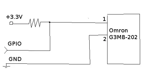
- I want to connect SSR (Omron G3MB-202P) to Raspberry GPIO.
This SSR has one NO contact (NO means "normally opened", i.e. it closes on high (3.3-5V) voltage). Can I use such a schema to provide high voltage on SSR when GPIO is closed (set 0) and low voltage on SSR when GPIO is opened (set 1):
Asked
Active
Viewed 2,543 times
3

user2455668
- 31
- 1
- 2
-
A NO switch where the resistor sources and the closed switch sinks is called "open drain" in the gpio world. It is a configuration option. – PaulF8080 Jul 07 '17 at 00:32
3 Answers
1
You could program the GPIOs to be sourcing or sinking. This depends on how you want your SSR relay to act.
If your question was about the default state of GPIOs, certain GPIO pins on Raspberry Pi are high when power is applied to the Pi and others are low by default.
Ameer
- 415
- 3
- 10
-
"certain GPIO pins on Raspberry Pi are high when power is applied to the Pi and others are low by default" is FALSE. All GPIO are **inputs** by default, although they may have a pull-up or pull-down. – Milliways Jul 06 '17 at 11:19
-
References: https://www.raspberrypi.org/forums/viewtopic.php?f=44&t=35321 & https://raspberrypi.stackexchange.com/questions/32639/why-are-some-gpio-pins-high-when-the-raspberry-pi-boots-up – Ameer Jul 10 '17 at 07:38
-
And your point is? The first link may have been true in 2013, but Foundation documentation differs, and it is simple to verify the fact that all pins are input. The accepted answer to the 2nd (by joan) agrees with my Comment. It is, or course, possible to set some pins to output by customising Device Tree settings, but by default **all GPIO are inputs**. – Milliways Jul 10 '17 at 08:01
-
0
About 2) I doubt you can reverse your signal with this shematic.
If you want to swap these values in an electronic manner, you will need a NOT logic gate.
This gate can be a specific chip, or can be made with a single transistor, using this kind of shematic :
 as described here :
http://www.electronics-tutorials.ws/logic/logic_4.html
Other implementation can be found here : https://en.wikipedia.org/wiki/Inverter_(logic_gate)
as described here :
http://www.electronics-tutorials.ws/logic/logic_4.html
Other implementation can be found here : https://en.wikipedia.org/wiki/Inverter_(logic_gate)
Note : it may be easier to revert this signal directly in the code, rather than soldering extra components ;)
Technico.top
- 1,406
- 13
- 20
-
1The path from "A" to ground is a one diode drop. You need a current limiting resistor just like an LED(diode). – PaulF8080 Jul 11 '17 at 05:04
0
The Pi GPIO can "source" when high or "sink" when low. This is default setting. The GPIO can safely source or sink 16mA.
GPIO are NOT relays, and "open" or "closed" are meaningless concepts.
In addition GPIO can have a pull-up or pull-down. This is a high value resistor ~50kΩ - most have pull-up by default see http://www.panu.it/raspberry/ . This can be disabled if not wanted e.g. if driving high impedance circuitry, but is only relevant if the GPIO is configured as an input.
No amount of fiddling with resistors is going to change the logic state, but I do not see why you would want to do this, just invert logic in your code.
It is also unclear from your question what you intend to control with the SSR. Are you aware that these are only suitable for AC loads?
Milliways
- 58,054
- 29
- 98
- 195
-
I assumed raspberry pi's output acts as output of any programmable logic controllers (for example omron CP1-E, which has relay or npn/pnp transistor switch as output). I want to switch with SSR solenoid valve which has 220AC on its input. Normally opened contact is a problem if wire is interrupted... In this case SSR would be opened, so solenoid valve would be opened too. I planned to use RPI as watering controller in my garden. Thank you for you explanations – user2455668 Jul 05 '17 at 07:22