1

I have a raspberry pi 2 Model B v1.1 and 7 color flash sensor. I want to flash the led to get my hand into practice. This is my first program with raspberry pi and unfortunately i failed to flash the led.

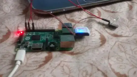
I am not using breadboard. I am using pi pin. For that i have used three female-female wire. One for connecting to 5v, one to ground and one to 11 number pin as a channel for supplying high or low voltage so when i use GPIO.output(11,True) led will flash. But it is not working. Here is my code.

7colorflash.py

import RPi.GPIO as GPIO
import time


GPIO.setmode(GPIO.BOARD)
mode = GPIO.getmode()
if mode == GPIO.BOARD:
    GPIO.setup(12,GPIO.OUT)
    GPIO.output(12,True)
    GPIO.output(12,False)
elif mode == GPIO.BCM:
    GPIO.setup(18,GPIO.OUT)
    GPIO.output(12,True)
    GPIO.output(12,False)
else:
    print('None')
GPIO.cleanup()

I have attached an image to show the connection. wire connected to 5v is in number 2 pin, ground in number 6 pin and channel number 11 is used.

enter image description here

What might be the cause for not flashing the led?
goldilocks
  • 58,187
  • 17
  • 111
  • 227
Tushant
  • 111
  • 2
  • Are you sure this device is safe to connect to a 3V3 GPIO. Where are its specs? – joan Oct 18 '16 at 08:53
  • 343 GPIO? Sorry i did not get you – Tushant Oct 18 '16 at 08:55
  • The device is powered by 5V, but the GPIO pins output 3.3V logic. You need to find out if the device is compatible with that. – goldilocks Oct 18 '16 at 09:13
  • oh sorry its my mistake I wrote number 1 pin in the question but i have connected it to number 2 pin and is not working. Sorry for my mistake in question. – Tushant Oct 18 '16 at 09:17
  • **Where are the 7 color flash sensor specifications?** – joan Oct 18 '16 at 09:22
  • 1
    "Connected to pin number 2" -> If you are still talking about the power that's not the issue. The issue is *the GPIO pin*, which you've referred to as 11. That's a 3.3V signal. If you do not have the specs and cannot identify the device but have everything else right, then this is likely the problem. – goldilocks Oct 18 '16 at 09:24
  • @goldilocks Sir i am using Raspberry PI 3 model and did the connection correctly. Setup 1 -> Problem which i am facing is when i connect LED to pin 11 without connecting it to pin 1 the light which i get from the LED after running the code is very low after running the code. Setup 2 -> On the other hand when i connect it to pin 1 along with pin 11 and GND i am getting continuous light from the led flash with high brightness which seems like the python code won't work at all for the second setup. – Shantanu Nandan Jan 17 '18 at 19:24

2 Answers2

0

I can think of the following.

  • Broken LED
  • Not connected to pin 11
  • Not driving the LED according to its specifications
  • LED connected back to front
joan
  • 70,096
  • 5
  • 71
  • 105
0

As per this, there are two commonplace ways of conceiving of the board pin numbers. Based on your photograph, you are assuming the BOARD numbering scheme, but you have not actually specified one way or the other.

While it says there setting that is mandatory, it could be importing the module under an alias (GPIO) sets it for you (or there actually is a default and setting it isn't so "mandatory"). I do not use python so don't know. You should try an if/else clause to test the value of GPIO.getmode() against GPIO.BOARD, GPIO.BCM, or None to see which it is.

If it is GPIO.BCM that is not pin 11, that is pin 18 (or perhaps 17, if you started counting from 1, it is hard to tell which row that connection is on).

goldilocks
  • 58,187
  • 17
  • 111
  • 227
  • so before setting the mode i have to do GPIO.getmode(). If mode == GPIO.BOARD i have to use number 11 pin as a channel and if mode equals to BCM use channel 17 ? – Tushant Oct 18 '16 at 09:28
  • Presuming you were counting from 1 and that connection is the inside row yes. This is about the number you would use in the code when the connector is where it is now. There's a diagram and more explanation here: http://raspberrypi.stackexchange.com/q/12966/5538 – goldilocks Oct 18 '16 at 09:32
  • I have now used 12 pin(BOARD) and 18 for BCM. Still it is not working. If i did not set GPIO at first before getmode() i get an error. With above code it is not working too. – Tushant Oct 18 '16 at 09:50
  • Then unless you can determine what logic level the device is compatible with it is probably because it is supposed to be used with 5V *logic*. The logic level and the supply power are not necessarily the same, but if they are, then that device won't work directly with the Pi, because while it has a few 5V pins to provide *power*, the logic of the GPIOs is 3.3V. Devices/sensors sold for the Arduino are usually 5V logic... – goldilocks Oct 18 '16 at 09:56
  • ...Sometimes they are sold "for the Arduino or Raspberry Pi" but this is ambiguous -- it could mean they work with either, but it could also be sneaky in that in fact a level shifter or something similar is actually needed for one or the other. More about that here: http://raspberrypi.stackexchange.com/a/49775/5538 – goldilocks Oct 18 '16 at 09:56